|
|
|
|
|
Introduction |
Major and minor losses associated with pipe flow in piping networks helps in determining the pumping power requirements, material and fittings selection. A good understanding of such losses helps engineers in designing optimum fluid distribution systems process plants etc . |
|
|
|
|
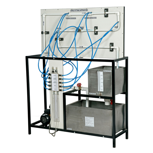
This apparatus is designed to introduce students to minor flow losses(Fittings) in Pipes.The following types of pipe fittings are generally provided with the apparatus |
|
|
|
|
-
Elbow
-
Bend
-
Sudden Expansion
-
Sudden Contraction
-
Valve
|
|
|
|
|
A flow control valve permits variation of flow rate through the circuit. Pressure tapings are incorporated so that the head loss characteristics of each fittings may be measured.These tapings are connected to an manometer bank incorporating a manifold with air bleed valve. The circuit and manometer are attached to a support ramework . |
|
|
|
Specifications |
-
Box Dimensions : 1000 X 500 X 1600 mm.
-
U- tube manometer : 300-0-300 (Mercury filled).
-
Number of fittings : 5 Nos.
-
Sump tank capacity : 100 litres MOC: ElectroplatingTank (PVC).
-
Volumetric tank capacity : 40 litres. MOC: SS-304 with Matt Buffing.
-
Pump : Monoblock type, 0-60 litre/min , Motor 0.5 HP.
-
Piping with necessary Valves and Fittings.
-
Digital Stop Watch with 1/10 second Accuracy.
-
Detailed Technical Manual and On-site demo.
|
|
|